Tuesday, January 27, 2015

Induction Suppression

Controlling a Motor or Solenoid
Inductive loads can best be defined as anything with a magnetic coil, such as a motor, solenoid, or a transformer. Controlling an inductive load using our relay controllers requires the use of induction suppression capacitors. The purpose of this capacitor is to absorb the high voltages generated by inductive loads, blocking them from the contacts of the relay. Without this capacitor, the lifespan of the relay will be greatly reduced. Induction can be so severe that it electrically interferes with the microprocessor logic of our controllers, causing relay banks to shut themselves down unexpectedly. In the case of USB devices, customers may experience loss of communications until the device is reconnected to the USB port.


Easy to install
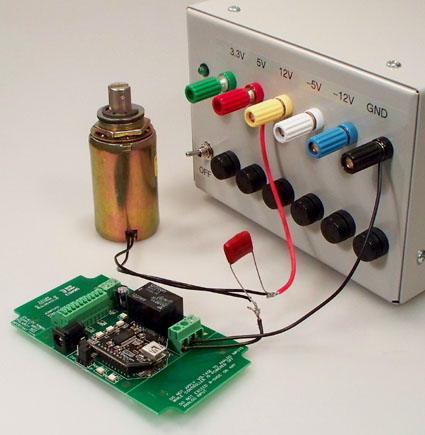
As you can see from the diagram above, an induction suppression capacitor is very easy to install. The capacitor should be located as close to the relay controller as possible, and is connected in parallel with the load you are trying to control. Induction suppression capacitors are NOT polarized, and may be used in either AC or DC applications.


Choosing the Right Capacitor
Choosing the correct induction suppression capacitor is simply a matter of choosing the maximum voltage requirement of the device you are trying to control. During checkout you will have the opportunity to purchase capacitors.

Resistive Loads
Unlike inductive loads, resistive loads such a incandescent lights and element heaters (without a fan), do NOT require an induction suppression capacitor, and will NOT benefit from its use.

Tuesday, January 20, 2015

Choosing the Proper Amperage

Relays often have two ratings: AC and DC.  These rating indicate how much power can be switched through the relays.  This does not necessarily tell you what the limits of the relay are.  For instance, a 5 Amp relay rated at 125VAC can also switch 2.5 Amps at 250VAC.  Similarly, a 5 Amp relay rated at 24VDC can switch 2.5 Amps at 48VDC, or even 10 Amps at 12VDC.

Volts x Amps = Watts - Never Exceed Watts!
An easy way to determine the limit of a relay is to multiply the rated Volts times the rated Amps.  This will give you the total watts a relay can switch.  Every relay will have two ratings: AC and DC.  You should determine the AC watts and the DC watts, and never exceed these ratings.


Example Calculations
AC Volts x AC Amps = AC Watts
DC Volts x DC Amps = DC Watts
Example:
A 5-Amp Relay is Rated at 250 Volt AC
5 x 250 = 1,250 AC Watts
Example:
A 5-Amp Relay is Rated at 24 Volts DC
5 x 24 = 120 DC Watts
When switching AC Devices, make sure the AC watts of the device you are switching DOES NOT exceed 1,250 when using a 5-amp relay.
If you are switching DC devices, make sure the DC watts of the device you are switching DOES NOT exceed 120 when using a 5-amp relay.

Resistive & Inductive Loads
Relays are often rated for switching resistive loads.  Inductive loads can be very hard on the contacts of a relay.  A resistive load is a device that stays electrically quiet when powered up, such as an incandescent light bulb.  An inductive load typically has a violent startup voltage or amperage requirement, such as a motor or a transformer.


Startup & Runtime Loads
Inductive loads typically require 2-3 times the runtime voltage or amperage when power is first applied to the device.  For instance, a motor rate at 5 Amps, 125 VAC will often require 10-15 amps just to get the shaft of the motor in motion.  Once in motion, the motor may consume no more than 5 amps.  When driving these types of loads, choose a relay that exceeds the initial requirement of the motor.  In this case, a 20-30 Amp relay should be used for best relay life.

Tuesday, January 13, 2015

Switch Using Multiple Relays

A more complex switching operation may need the use of more than one relay to perform the task.  In this case we will look at using two relays to switch a single item.  Our example will be switching an irrigation system and we have two criteria to meet before we want the water to flow.

For our example we will use a 2-channel ProXR Lite board.  This board has two relay and eight Analog to Digital inputs onboard.  We will connect sensors to the inputs and have them control the relays. 

First we have the basic need that the soil needs to be dry before we switch on the irrigation system.  We will then put a moisture sensor in the ground and connect it to input 1 on the board.  In our programming input 1 will switch relay 1 when the soil is at a certain moisture level (dry).  The second need we have is that we don’t want to irrigate in the heat of the day.  We will connect a light sensor to input 2 of our board and program it to switch relay at dusk. 

As you can see by the diagram, both relays will need to be energized to trigger the light or irrigation in our example.  The electrical signal will come into the common and when the arm of relay 1 swings to the NO side (the moisture sensor activates) it will allow the signal to now flow to the common of the second relay.  When the light sensor in our example says it’s the correct darkness it will swing the arm to the NO position on Relay 2 and allow the signal to activate the light or irrigation.

This example is for irrigation but it can be used in many different applications where your switching is controlled by multiple variants using automatic or manual mechanisms. 

To achieve this we have a couple of options available.  You can purchase a 2-channel computer controlled relay and write the program yourself.  you can find these on our site at: http://www.relaypros.com/Relay/Relay/CAT_RELAY2.  Another alternative is to purchase a Reactor Relay which operates from the sensor inpurts.  You simply configure where the trigger points will be with no programming involves.  You can find the 2-channel Reactor boards at: http://www.relaypros.com/Relay/Relay/CAT_RELAY2_REACTOR.

Tuesday, January 6, 2015

Introduction to Relays

A relay is best defined as a switch that is operated by an electromagnet.  A relay controller is a device that is used to control a bank of switches.  A relay controller works by turning on and off magnetic coils under logic control.  A computer controlled relay driver allows your computer to send simple commands to activate a switch or a group of switches.  Relays are ideally suited for controlling everything from lights and motors to telecommunication, audio, and video signals.

The boards at Relay Pros allow you to switch electrical equipment from a computer via Wired, Wireless or Network communications.  There are many advantages to using the different interfaces and we will look at these in future posts.

Relays typically have two or three connections: Common, Normally Open, and Normally Closed.   The Common is the part of the relay that actually makes a mechanical movement.  By default, many relays have their common (COM) lead connected to the normally closed lead (NC).  When the electromagnet is energized, the COM disconnects from the NC and reconnects to the Normally Open lead (NO).  When the relay is deactivated, the COM reconnects to the NC (see diagrams)
.

Relay Types Available from Relay Pros
SPDT or Single Pole Double Throw Relays have three connections.  Common, Normally Open, and Normally Closed.  When the relay is off, the common is connected to the normally closed connection of the relay.  When the relay coil is energized, the Common swings over to the Normally Open Connection.

Available in our 5, 10 and 20 amp versions.
SPST Single Single Single Throw Relays simply connect two wires together.  The COMMON is the moving part of the relay that comes in contact with the Normally Open when the coil to the relay is energized. 

Available in our 30-Amp versions

DPDT Double Pole Double Throw Relays have a single coil with two arms that move at the same time.  There are two completely separate SPDT switch mechanisms inside a DPDT relay.  DPDT relays are most commonly used for signal switching applications, but can be found in high power switching applications. 

Available in our 1, 3, and 5 amp versions starting with the 4-channel boards.